Preprocessing: FreeCAD/OpenSCAD + Gmsh
Introduction
There are several open source tools for preparing 2D and 3D finite element meshes like Salome, FreeCAD, Gmsh, Netgen, etc. Most of them are GUI based geometrical modeling and meshing environments/tools but they also usually allow using their libraries in user scripts. Some of the above mentioned tools are handy for solid modeling, some of them are great for meshing. This tutorial shows how to combine solid geometry modeling functions provided by FreeCAD or OpenSCAD with meshing functions of Gmsh.
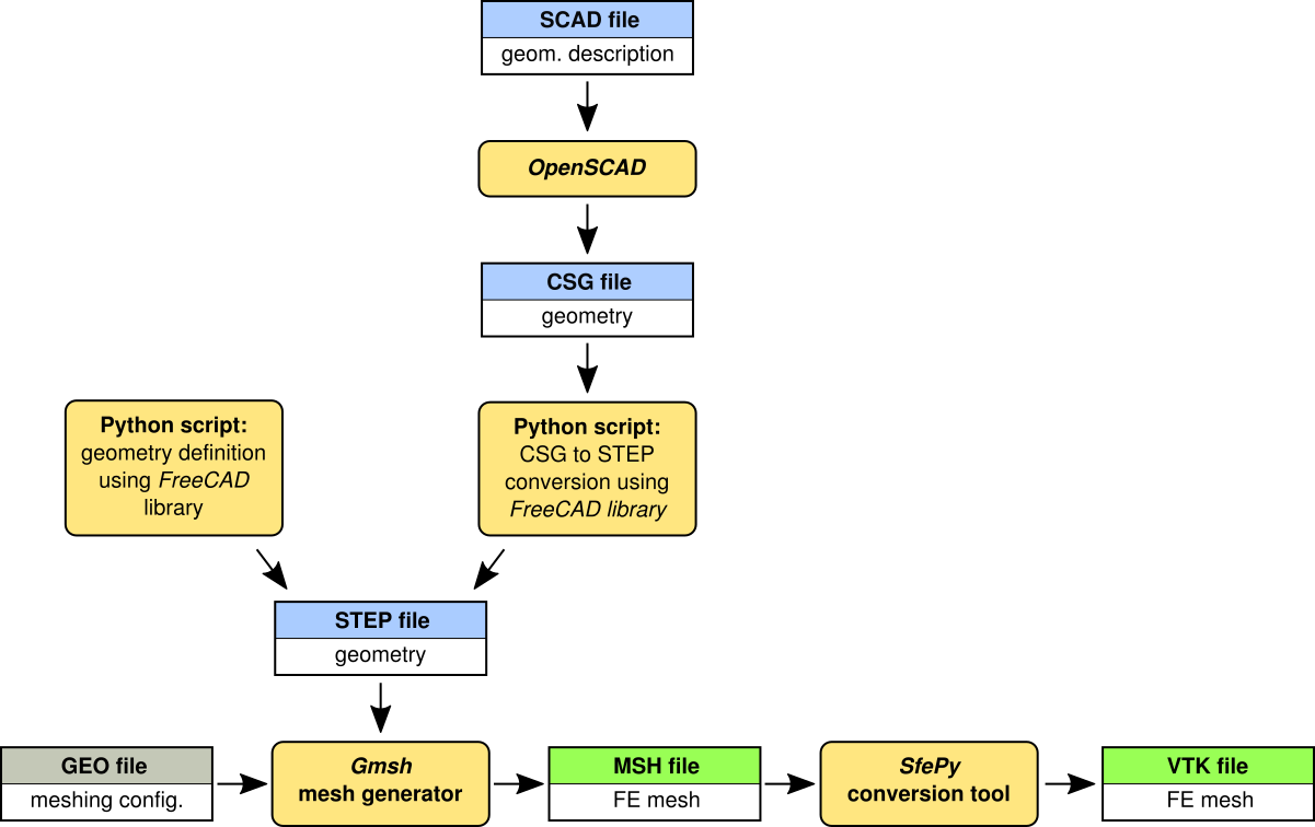
The collaboration of modeling, meshing and conversion tools and the workflow are illustrated in the following scheme.
Creating geometry using FreeCAD
Functionalities of FreeCAD are accessible to Python and can be used to define geometrical models in simple Python scripts. There is a tutorial related to Python scripting in FreeCAD.
The first step in creating a Python script is to set up a path to the FreeCAD libraries and import all required modules:
1import sys
2FREECADPATH = '/usr/lib/freecad/lib/'
3sys.path.append(FREECADPATH)
4
5from FreeCAD import Base, newDocument
6import Part
7import Draft
8import ProfileLib.RegularPolygon as Poly
Now, a new empty FreeCAD document can be defined as:
doc = newDocument()
All new objects describing the geometry will be added to this document.
In the following lines a geometrical model of a screwdriver handle will be
created. Let’s start by defining a sphere and a cylinder and join these objects
into the one called uni:
 1radius = 0.01
 2height = 0.1
 3
 4cyl = doc.addObject("Part::Cylinder", "cyl")
 5cyl.Radius = radius
 6cyl.Height = height
 7
 8sph = doc.addObject("Part::Sphere", "sph")
 9sph.Radius = radius
10
11uni = doc.addObject("Part::MultiFuse", "uni")
12uni.Shapes = [cyl, sph]
Create a polygon, revolve it around the z-axis to create a solid and use the
result as the cutting tool applied to uni object:
 1ske = doc.addObject('Sketcher::SketchObject', 'Sketch')
 2ske.Placement = Base.Placement(Base.Vector(0, 0, 0),
 3                               Base.Rotation(-0.707107, 0, 0, -0.707107))
 4Poly.makeRegularPolygon('Sketch', 5,
 5                        Base.Vector(-1.2 * radius, 0.9 * height, 0),
 6                        Base.Vector(-0.8 * radius, 0.9 * height, 0))
 7
 8cut = doc.addObject("PartDesign::Revolution", "Revolution")
 9cut.Sketch = ske
10cut.ReferenceAxis = (ske, ['V_Axis'])
11cut.Angle = 360.0
12
13dif = doc.addObject("Part::Cut", "dif")
14dif.Base = uni
15dif.Tool = cut
Create a cylinder, make a polar array of the cylinder objects and subtract it from the previous result:
 1cyl1 = doc.addObject("Part::Cylinder", "cyl1")
 2cyl1.Radius = 0.2 * radius
 3cyl1.Height = 1.1 * height
 4cyl1.Placement = Base.Placement(Base.Vector(-1.1 * radius, 0, -0.2 * height),
 5                                Base.Rotation(0, 0, 0, 1))
 6
 7arr = Draft.makeArray(cyl1, Base.Vector(1, 0, 0), Base.Vector(0, 1, 0), 2, 2)
 8arr.ArrayType = "polar"
 9arr.NumberPolar = 6
10
11dif2 = doc.addObject("Part::Cut", "dif2")
12dif2.Base = dif
13dif2.Tool = arr
Create a middle hole for the screwdriver metal part:
1cyl2 = doc.addObject("Part::Cylinder", "cyl2")
2cyl2.Radius = 0.3 * radius
3cyl2.Height = height
4
5dif3 = doc.addObject("Part::Cut", "dif3")
6dif3.Base = dif2
7dif3.Tool = cyl2
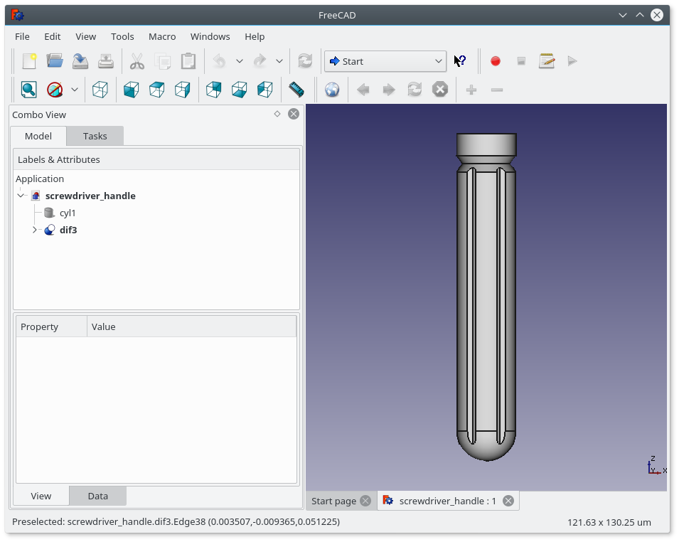
Finally, recompute the geometry, export the part to the STEP file and save the document in FreeCAD format (not really needed for subsequent mesh generation, but may be useful for visualization and geometry check):
1doc.recompute()
2
3Part.export([dif3], 'screwdriver_handle.step')
4
5doc.saveAs('screwdriver_handle.FCStd')
A finite element mesh can be generated directly in FreeCAD using MeshPart
module:
1import MeshPart
2
3mesh = doc.addObject("Mesh::Feature", "Mesh")
4mesh.Mesh = MeshPart.meshFromShape(Shape=dif3.Shape, MaxLength=0.002)
5mesh.Mesh.write("./screwdriver_handle.bdf", "NAS", "mesh")
The meshing function of MeshPart module is limited to triangular grids so
it is better to use Gmsh mesh generator which can provide triangular and
quadrilateral meshes in 2D or tetrahedral and hexahedral meshes in 3D. Gmsh
allows to control the meshing process through a wide range of parameters.
Meshing by Gmsh will be described in section Gmsh - generating finite element mesh.
The example of screwdriver handle:
screwdriver_handle.py.
There are two simple ways how to discover Python calls of FreeCAD functions.
You can enable “show script commands in python console” in
Edit->Preferences->General->Macro and the Python console by selecting
View->Views->Python Console and all subsequent operations will be printed in
the console as the Python code. The second way is to switch on the macro
recording function (Macro->Macro recording ...) which generates a Python
script (FCMacro file) containing all the code related to actions in the
FreeCAD graphical interface.
Creating geometry using OpenSCAD
The alternative tool for solid geometrical modeling is OpenSCAD - “The
Programmers Solid 3D CAD Modeller”. It has its own description language based on
functional programming that is used to construct solid models using geometrical
primitives similar to FreeCAD. Solid geometries can be exported to several
file formats including STL and CSG. OpenSCAD allows solid modeling based
on Constructive Solid Geometry (CSG) principles and extrusion of 2D objects into
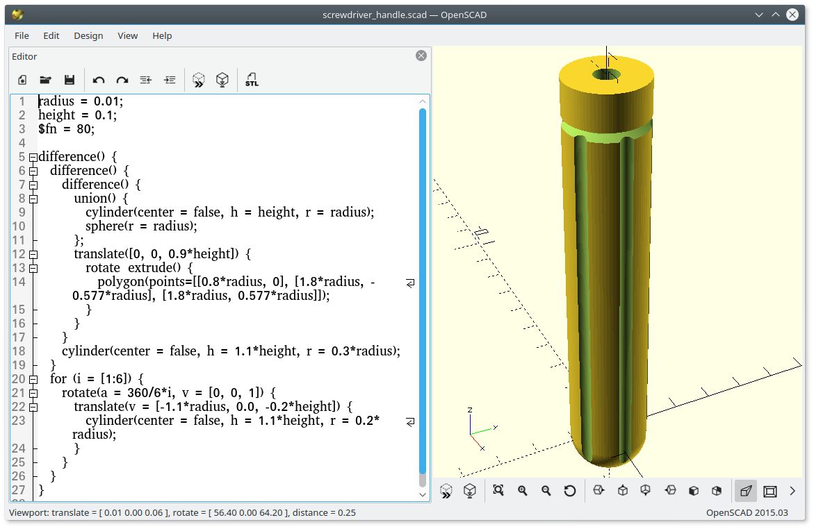
3D. The model of a screwdriver handle presented in the previous section can be
defined in OpenSCAD by the following code
(screwdriver_handle.scad):
 1radius = 0.01;
 2height = 0.1;
 3$fn = 50;
 4
 5difference() {
 6  difference() {
 7    difference() {
 8      union() {
 9        cylinder(center=false, h=height, r=radius);
10        sphere(radius);
11      };
12      translate([0, 0, 0.9*height])
13        rotate_extrude()
14          polygon([[0.8*radius, 0], [1.8*radius, -0.577*radius], [1.8*radius, 0.577*radius]]);
15    }
16    cylinder(center=false, h=1.1*height, r=0.3*radius);
17  }
18  for (i = [1:6]) {
19    rotate([0, 0, 360/6*i])
20      translate([-1.1*radius, 0.0, -0.2*height])
21        cylinder(center=false, h=1.1*height, r=0.2*radius);
22  }
23}
To generate a finite element mesh of the solid geometry the model must be exported to a suitable file format. OpenSCAD has limited export options, but by using FreeCAD import/export functions, it is possible to find a workaround. The OpenSCAD model can be exported to the CSG file format and FreeCAD can be used as a mesh converter to the STEP format:
 1import sys
 2sys.path.append('/usr/lib/freecad/lib/')
 3sys.path.append('/usr/lib/freecad/Mod/OpenSCAD/')
 4
 5import FreeCAD
 6import Part
 7import importCSG
 8
 9importCSG.open('screwdriver_handle.csg')
10Part.export([FreeCAD.ActiveDocument.Objects[-1]], 'screwdriver_handle.step')
Gmsh - generating finite element mesh
Gmsh can create finite element meshes using geometrical models imported from STEP, IGES and BRep files (has to be compiled with OpenCASCADE support).
The following GEO file imports screwdriver_handle.step file and defines
a field controlling the mesh size
(screwdriver_handle.geo):
1Merge "screwdriver_handle.step";
2
3Field[1] = MathEval;
4Field[1].F = "0.002";
5Background Field = 1;
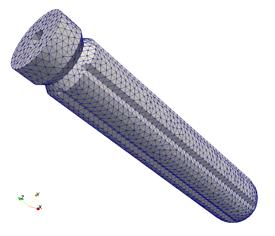
Now, run Gmsh generator and export the mesh into the MSH format in which all surface and volumetric elements are stored:
gmsh -3 -format msh -o screwdriver_handle.msh screwdriver_handle.geo
By converting the MSH file into the VTK format using
sfepy-convert:
sfepy-convert -d 3 screwdriver_handle.msh screwdriver_handle.vtk
the surface elements are discarded and only the volumetric mesh is preserved.
Note: planar 2D meshes
To create a planar 2D mesh, such as
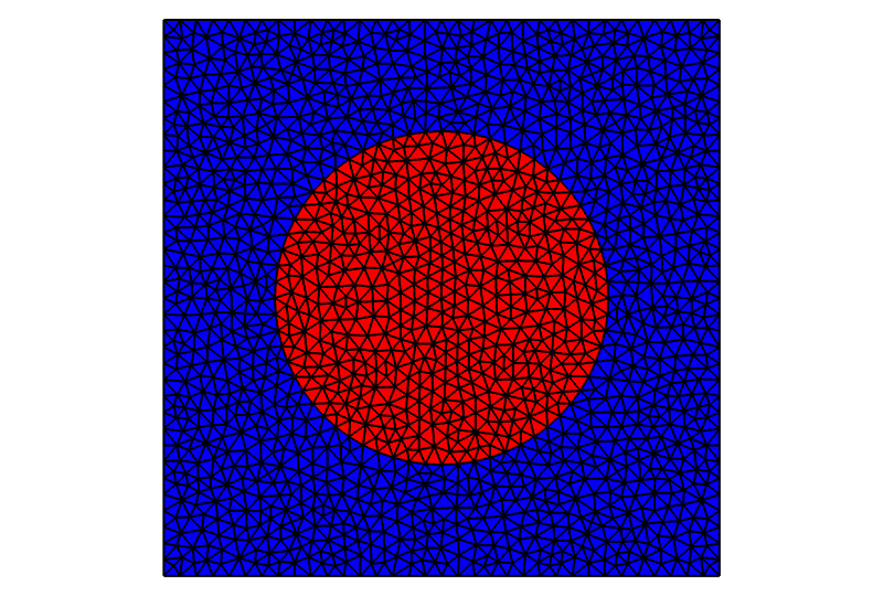
that can be described by this
Gmsh code, the mesh generator can be called as follows:
gmsh -2 -format msh -o circle_in_square.msh circle_in_square.geo
This, however is not enough to create a truly 2D mesh - the created mesh
vertices still have the third,  , component which is equal to zero. In
order to remove the third component, use:
, component which is equal to zero. In
order to remove the third component, use:
sfepy-convert --2d circle_in_square.msh circle_in_square.h5
Now, in the resulting circle_in_square.h5, each vertex has only two
coordinates. Another way of generating the 2D mesh is to use the legacy VTK
format as follows:
gmsh -2 -format vtk -o circle_in_square.vtk circle_in_square.geo
sfepy-convert circle_in_square.vtk circle_in_square.h5
This is due to the fact that the legacy VTK does not support 2D vertices and so
the VTKMeshIO reader tries to
detect the planar geometry by comparing the components to zero - the
--2d option of sfepy-convert is not needed in this case.
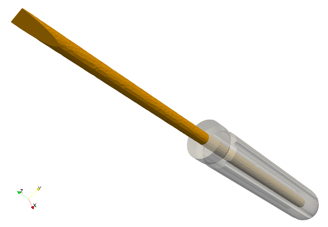
Multipart models
Meshing models composed of parts with different material groups is a little bit tricky task. But there are some more or less general ways of doing that. Here, the method using functions of Gmsh for periodic meshes will be shown.
The screwdriver handle example is extended by adding a screwdriver shank. The new part is composed of a cylinder trimmed at one end:
 1cyl3 = doc.addObject("Part::Cylinder", "cyl3")
 2cyl3.Radius = 0.3 * radius
 3cyl3.Height = height
 4cyl3.Placement = Base.Placement(Base.Vector(0, 0, height),
 5                                Base.Rotation(0, 0, 0, 1))
 6
 7tip1 = doc.addObject("Part::Box", "tip1")
 8tip1.Length = radius
 9tip1.Width = 2 * radius
10tip1.Height = 3 * radius
11tip1.Placement = Base.Placement(Base.Vector(0, -radius, 1.71 * height),
12                                Base.Rotation(Base.Vector(0, 1, 0), -10),
13                                Base.Vector(0, 0, 3 * radius))
14
15tip2 = doc.addObject("Part::Mirroring", "tip2")
16tip2.Source = tip1
17tip2.Normal = (1, 0, 0)
18
19tip3 = doc.addObject("Part::MultiFuse", "tip3")
20tip3.Shapes = [tip1, tip2]
21
22dif4 = doc.addObject("Part::Cut", "dif4")
23dif4.Base = cyl3
24dif4.Tool = tip3
25
26uni2 = doc.addObject("Part::MultiFuse", "uni2")
27uni2.Shapes = [cyl2, dif4]
The handle and shank are exported to the STEP file as two separated parts:
1doc.recompute()
2
3Part.export([dif3, uni2], 'screwdriver_full.step')
4doc.saveAs('screwdriver_full.FCStd')
The full screwdriver example (handle + shank):
screwdriver_full.py.
To create a coincidence mesh on the handle and shank interface, it is necessary to identify the interface surfaces and declare them to be periodic in the GEO file. The identification has to be done manually in the Gmsh graphical interface.
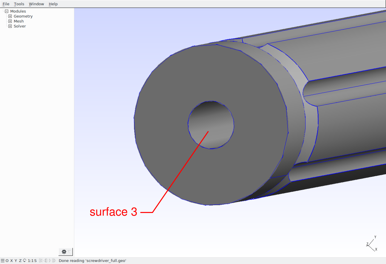
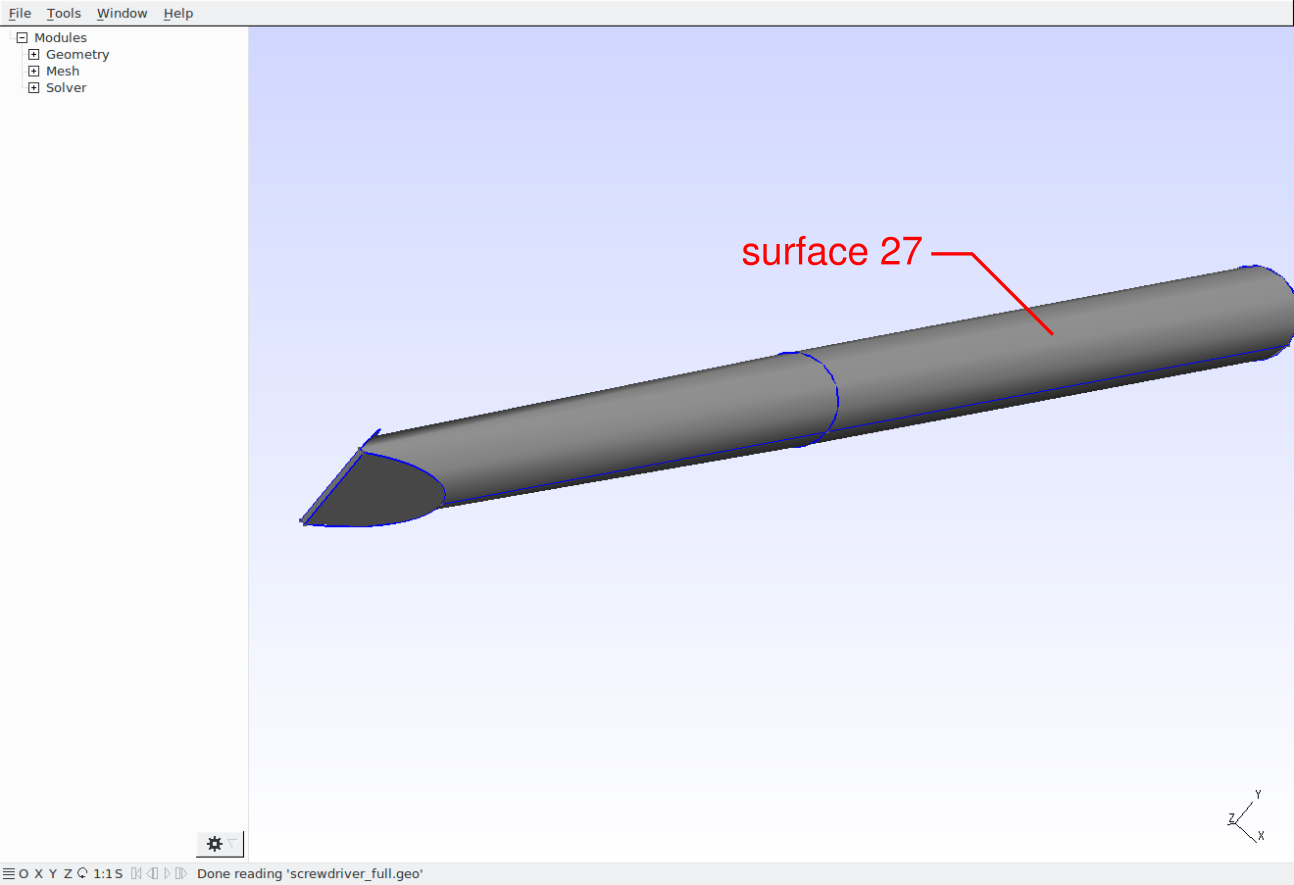
The input file for Gmsh is than as follows
(screwdriver_full.geo):
 1Merge "screwdriver_full.step";
 2
 3Periodic Surface 5 {7} = 26 {67};
 4Periodic Surface 3 {6, 2, -6, 7} = 27 {68, 69, -68, 67};
 5
 6Physical Volume(1) = {1};
 7Physical Volume(2) = {2};
 8
 9Field[1] = MathEval;
10Field[1].F = "0.0015";
11Background Field = 1;
where the first pair of periodic surfaces corresponds to the common circle faces (bottom of the shank) and the second pair to the common cylindrical surfaces. See Gmsh Reference manual for details on periodic meshing.
Using the above stated GEO file, Gmsh creates a mesh containing duplicate
vertices on the handle/shank interface. These duplicate vertices can be removed
during the conversion to the VTK format by giving --merge (or just -m)
argument to convert_mesh.py script:
sfepy-convert -m screwdriver_full.msh screwdriver_full.vtk
In order to extract the cells by the physical groups use the conversion script
with --save-per-mat argument:
sfepy-convert --save-per-mat screwdriver_full.vtk screwdriver.vtk
It produces screwdriver.vtk contaning the original mesh and screwdriver_matid_1.vtk, screwdriver_matid_2.vtk files containing only the cells of a given physical group and all vertices of the original mesh.
When using OpenSCAD, define the full screwdriver geometry as
(screwdriver_full.scad):
 1radius = 0.01;
 2height = 0.1;
 3$fn = 50;
 4
 5module tip() {
 6  rotate([0, -10, 0])
 7    translate([0, -radius, -3*radius])
 8      cube([radius, 2*radius, 3*radius], center=false);
 9}
10
11difference() {
12  difference() {
13    difference() {
14      union() {
15        cylinder(center=false, h=height, r=radius);
16        sphere(radius);
17      };
18      translate([0, 0, 0.9*height])
19        rotate_extrude()
20          polygon([[0.8*radius, 0], [1.8*radius, -0.577*radius], [1.8*radius, 0.577*radius]]);
21    }
22    cylinder(center=false, h=height, r=0.3*radius);
23  }
24  for (i = [1:6]) {
25    rotate([0, 0, 360/6*i])
26      translate([-1.1*radius, 0.0, -0.2*height])
27        cylinder(center=false, h=1.1*height, r=0.2*radius);
28  }
29}
30
31union() {
32  difference() {
33    translate([0, 0, height])
34      cylinder(center=false, h=height, r=0.3*radius);
35    translate([0, 0, 1.71*height + 3*radius])
36      union() {
37        tip();
38        mirror ([1, 0, 0]) tip();
39      }
40  }
41  cylinder(center=false, h=height, r=0.3*radius);
42}
and convert the CSG file to the STEP file by:
1importCSG.open('screwdriver_full.csg')
2top_group = FreeCAD.ActiveDocument.Objects[-1]
3Part.export(top_group.OutList, 'screwdriver_full.step')
Since the different tools for geometry definition have been used, the numbering of geometric objects may differ and the surface and edge numbers have to be changed in the GEO file:
Periodic Surface 5 {6} = 26 {66};
Periodic Surface 3 {5, 2, -5, 6} = 27 {67, 68, -67, 66};
Note: The numbering of objects may vary between FreeCAD, OpenSCAD and Gmsh versions.